101s
RC made reference materials explaining some basic yet complicated frequently encountered stuff like driving & dimming LEDs, impedance in audio circuits, and mic/instrument/line levels.
Impedance 101
Impedance is resistance across a path that includes capacitors and inductors.
- A capacitor blocks slow/DC signals but lets fast/high-frequency ones through
- An inductor does the opposite — it passes DC but chokes high-frequency signals
A circuit or amp output impedance and speaker's load impedance is an important relationship. When mismatched it can waste power or degrade the signal.
In an amp/speaker relationship, the ideal is to have the amp impedance much lower than the speaker impedance. This is called the damping factor.
A damping factor of 8 is good.
An amp doesn't just set the speaker in motion, it's a dynamically controlled relationship. If the amp impedance is too high, it loses that control, and the sound degrades as the speaker cone wobbles around restrained only by physical design.
- Running a 4Ω speaker on an amp rated for 8Ω minimum draws double the current. The amp runs hot, distorts, and can outright fail — either tripping protection circuits or burning output transistors. Do this long enough and you're buying a new amp.
- Going the other direction — a 16Ω speaker on an amp expecting 4Ω — won't blow anything up, but you're leaving most of your power on the table and potentially driving the amp into a region where its own distortion goes up significantly.
Multiple speakers compound this fast. Two 8Ω speakers wired in parallel present a 4Ω load. Get this wrong with a cheap amp and you'll see it thermally shut down mid-show, or worse.
Mic impedance mismatching is subtler but can be more insidious because it degrades signal before you've even amplified anything — you're corrupting the source.
The classic rule was impedance bridging: the mic preamp's input should be at least 5–10× higher impedance than the mic's output. This ensures maximum voltage transfer and doesn't load down the mic.
Dynamic mics (like an SM58) are low-impedance (~150–300Ω output) and fairly forgiving. Plug one into a high-impedance input (like a cheap guitar amp's instrument input) and you get high-frequency rolloff — the top end of the sound gets physically filtered out by the impedance mismatch acting like a passive low-pass filter.
Ribbon mics are where this becomes serious. Ribbons are extremely low impedance (sometimes under 30Ω) and the ribbon element itself is a literal strip of thin metal foil. Certain preamps — especially older ones or cheap ones — have poorly controlled input impedance that can interact badly with a ribbon. Some transformerless preamps can actually cause DC offset or reverse current conditions that physically stretch or tear the ribbon.
Phantom power (+48V) is the other major danger zone. Phantom is safe for condenser mics and most modern dynamic mics — it's balanced and equal on both signal pins. But:
- Unbalanced dynamic mics wired with certain adapters can have phantom voltage appear asymmetrically across the voice coil, potentially burning the coil out
- Vintage or cheap ribbon mics (without proper transformers) can have phantom voltage surge through the ribbon and vaporize it instantly
- Improperly wired cables with phantom enabled can send voltage somewhere it shouldn't go — into a preamp output, into a DI box's unprotected input, etc.
LEDs 101
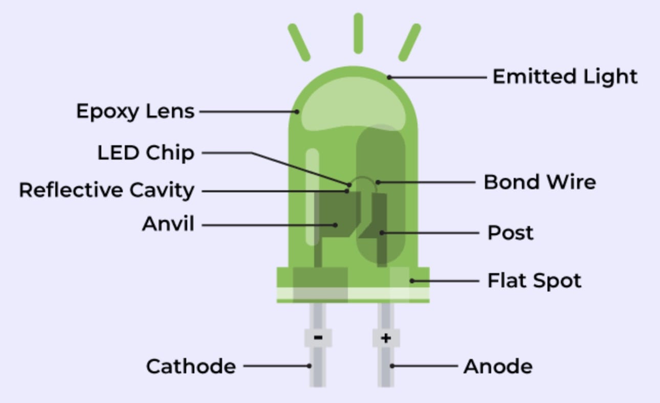
The anode wire extends into the epoxy/plastic housing of the LED and has small cup which houses a tiny semiconductor. a ~25µm diameter gold or aluminum "bond wire" bridges the semiconductor to the cathode pin.
The semiconductor in the cup of the anode creates the light, and is a "forward-biased p-n junction." This is just a way of describing the mechanism. At a certain voltage (~1.8–3.5V) the p-n junction is activated, releasing light. Brightness is proportional to current, and the forward voltage is a consequence of that current.
The behavior of an LED can be described using the Shockley diode equation. The important part to note is that this equation describes an exponential relationship, such that a tiny voltage increase can cause an exponential increase in current, making it impractical to control an LED via voltage.
So... LEDs are all fundamentally current-controlled devices.
Types of LEDs
High-power LEDs
Typically have associated datasheets that specify a drive current, and the forward voltage is listed as a result, with tolerances. Running these from a fixed voltage is risky, with small Vf variations between chips of the same model, or changes with temperature, translate directly into wildly different currents. These essentially require a CC (Constant current) driver.
Low-power LEDs
Typically run with a series resistor from a fixed voltage rail. The resistor functions as a crude current control.
Addressable LEDs
Have a CC driver integrated, to control current to each color channel. So from the outside they function as constant voltage design.
Strips and arrays
Strips and arrays also typically have resistors integrated, so again can be treated as constant voltage devices, though at the component level are still constant current.
Strips in detail (from https://www.ledsupply.com/blog/ultimate-guide-on-buying-led-strip-lights/)
DC flex strips
Simple. Supply 12-24V, the built-in resistors on the strip do the current limiting.
Can be dimmed with PWM.
Downsides:
- Resistors generate heat rather than light.
- Over long runs, end of strip can be visibly less bright. 24V strips can run longer, but same eventual result. This can be mitigated by powering from both ends, making sure power supply wire gauge is ample.
AC strips
Have miniature switching converters that rectify and regulate DC voltage. These are more limited in terms of cutting to length than DC strips.
Requires specifically matched leading or trailing edge triac dimmer.
Dimming
The most common LED dimming method is Pulse Width Modulation (PWM). A pulse wave is similar to a square wave, but has more variation. A square wave is defined is 50% low, 50% high. A pulse wave can be high/low in any proportion.
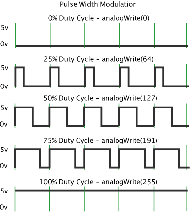
(from https://docs.arduino.cc/learn/microcontrollers/analog-output/)
An LED being controlled by a pulse wave at a high enough frequency exploits limitations in human perception, and appears to at 50% brightness, when in fact it is on a full brightness, but just 50% of the time. The cutoff for perception is around 50-60Hz. In cheaper or poorly designed PWM controls, the frequency of the on/off cycle is lower, e.g. 100Hz, which may not be obvious to the eye, but can leave people with headaches or become tiring. Better PWM controls cycle upwards of 1kHz.
References:
https://www.ledsupply.com/blog/understanding-led-drivers/
https://www.ledsupply.com/blog/dimming-leds-guide-how-to-tell-if-your-lights-are-dimmable/
mic-instrument-line levels 101
Mic level is the weakest. A microphone's output is tiny — we're talking millivolts. It's a fragile, low-amplitude signal that needs significant amplification before it's useful. This is what preamps exist to do — take mic level up to line level. The signal is also unbalanced in many cheaper implementations, making it susceptible to noise pickup over any meaningful cable length, which is why professional mics use balanced XLR connections.
Instrument level sits between mic and line, but it's a weird in-between that causes a lot of confusion. An electric guitar or bass puts out more voltage than a mic, but it's also very high impedance — typically 10kΩ to 1MΩ depending on the pickups. That high impedance means the signal is very sensitive to the input it connects to. Plug a guitar into a low-impedance input and the input loads down the pickups, sucking out high frequencies and killing the characteristic tone. This is why guitar amps and DI boxes have high-impedance instrument inputs — they're not just amplifying the signal, they're presenting the right impedance to let the pickup behave correctly.
Line level is the standard operating level for most audio gear — mixers, interfaces, effects processors, CD players, synthesizers. There are actually two standards: consumer line level at around −10dBV (used in home stereos, consumer gear) and professional line level at +4dBu (used in studios and live sound). These are about 12dB apart, which is roughly 4× the voltage. Plugging pro gear output into consumer gear input can clip it. Plugging consumer output into pro gear input means it arrives quieter than expected and you're amplifying more noise floor along with it.
Mic into a line input — the signal arrives way too quiet. You crank the gain to compensate, and now you're amplifying all the noise the cable and input stage picked up along the way. You get a usable signal buried in hiss.
Line into a mic input — the signal is massively too hot. It slams the preamp into hard clipping immediately. Sounds terrible, and depending on the preamp, sustained high levels can damage it.
Guitar into a line input — two problems at once. The level is wrong (instrument level is lower than line), and the impedance is wrong (line inputs are low impedance, which loads the pickups). You get a quiet, thin, tonally incorrect signal. This is why "just plug it into the interface's line input" doesn't work — you need the instrument/Hi-Z input.
Guitar into a mic input — impedance is still wrong, and now you're also dealing with a preamp designed for balanced low-impedance sources trying to handle an unbalanced high-impedance one. Noise, tone loss, and potential level issues all at once.
Synth or keyboard into an instrument input — a synth outputs true line level from a low-impedance output. Plugging it into a Hi-Z instrument input usually works okay but you're not getting the right impedance match, and on some interfaces it can sound slightly different than going into a proper line input.
Inkle Loom Basics
The Inkle loom is a relatively simple loom best-suited for weaving longer narrow pieces, but uses concepts that are built on by more complex looms. It's also really easy to make.
Screenshots taken from: https://www.youtube.com/watch?v=PhzBMYzPVW0
Useful for weaving reference: https://www.youtube.com/watch?v=8nYpfku1Yjw
There are tons of other videos and tutorials...
Pegs by placement (+ tension peg)
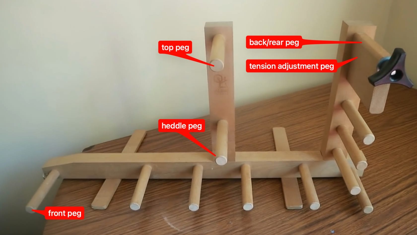
Pegs can be referred to by placement on machine. In this case the rear peg also serves as a tension peg. Tension can be adjusted in different ways. In this case, the rear peg shape functions as a crude cam (wikipedia), which increases tension by rotation, and is locked into place via pressure applied via the black knob.
In the most minimal form, a loom could consist of only 4 pegs. The additional pegs allow for taking up additional warp threads, allowing for longer pieces to made on a small loom, and also allow for specific placement of active weaving area, which has consequences for the quality of the final work.
Pegs by function
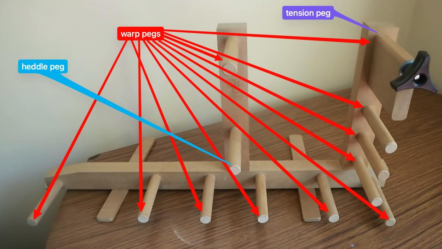
Pegs can also be referred to by their function. Warp pegs provide a wrapping path for the warp threads, while the heddle peg provides an anchor for heddle loops. The tension peg will by definition always be a warp peg, as it serves to provide tension to the warp threads.
The heddles
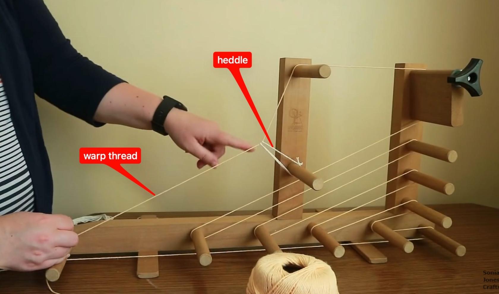
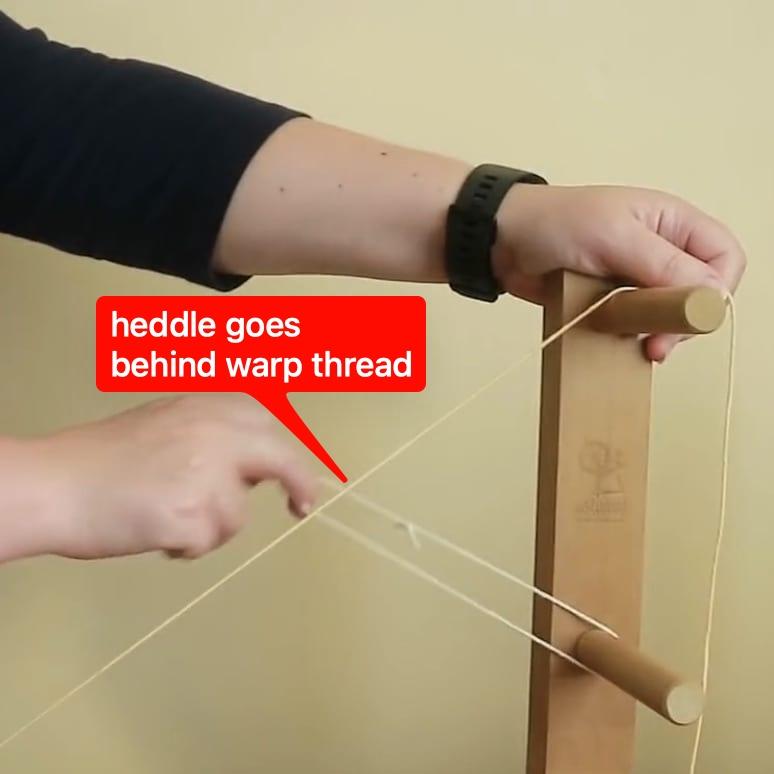
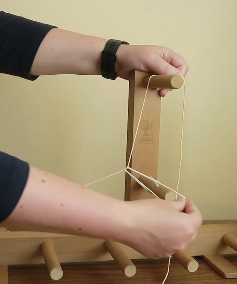
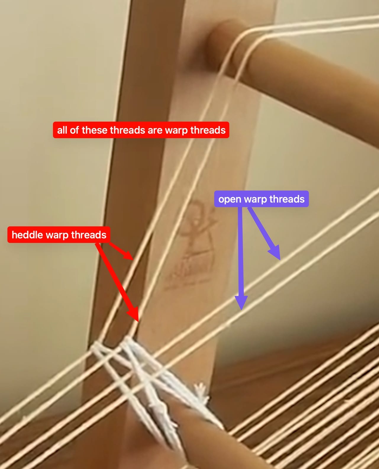
The heddle peg is the anchor for the heddles. Heddles are loops of thread that wrap around warp threads, apply tension, and most critically, change the path of some warp threads.
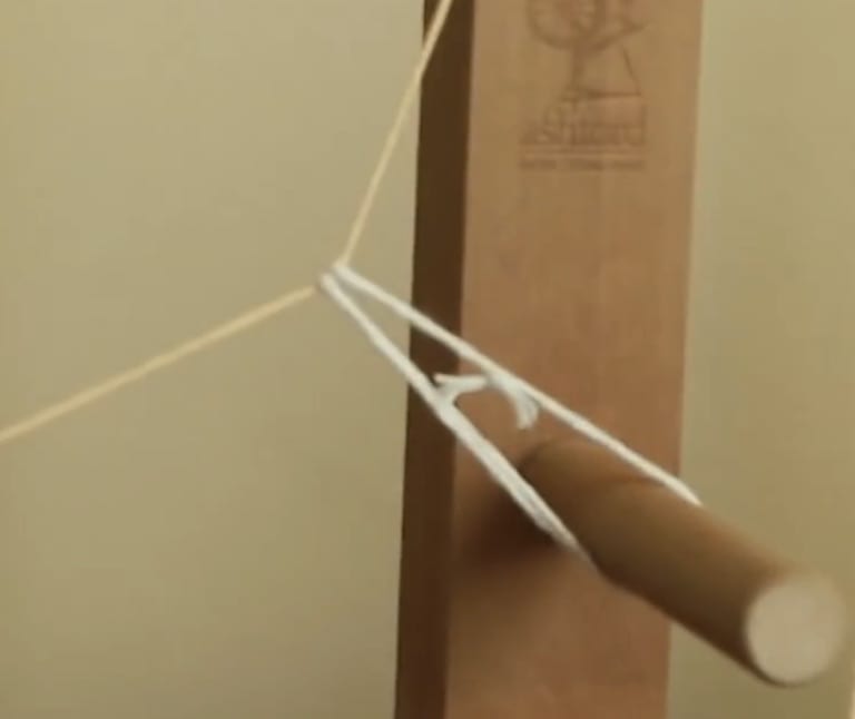
On an Inkle loom, heddles are simple loops of cord.
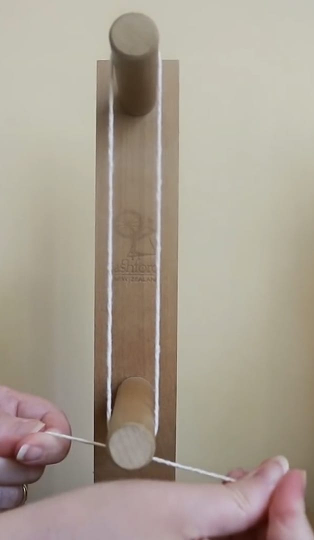
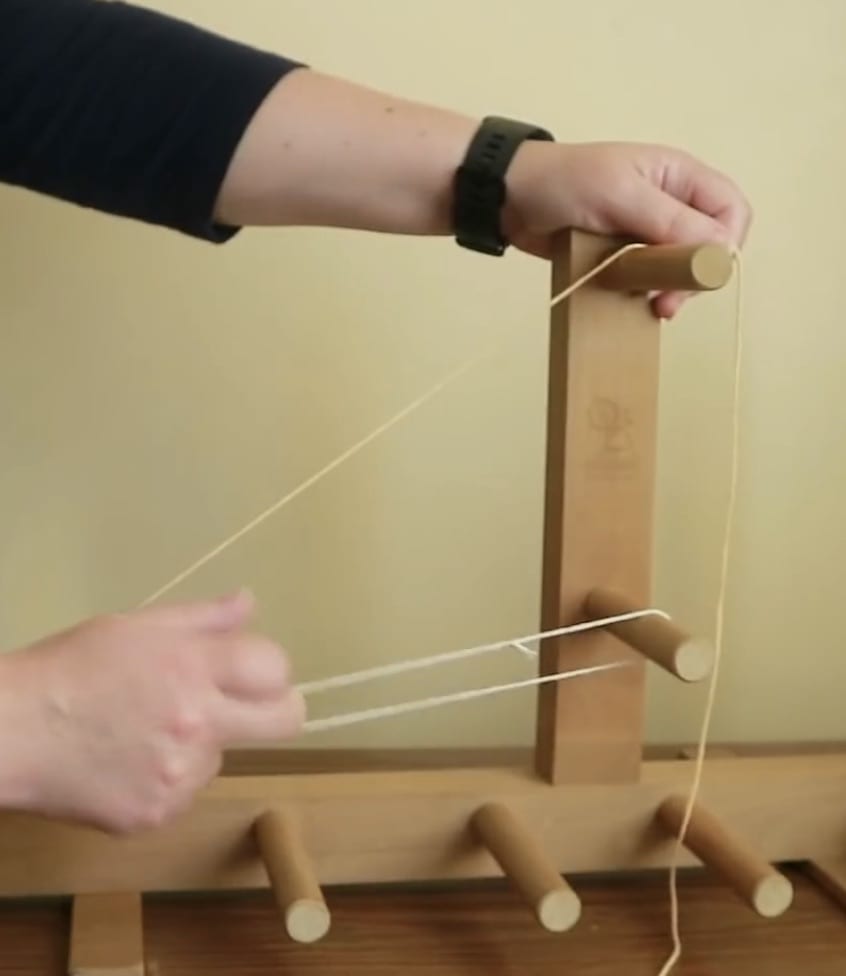
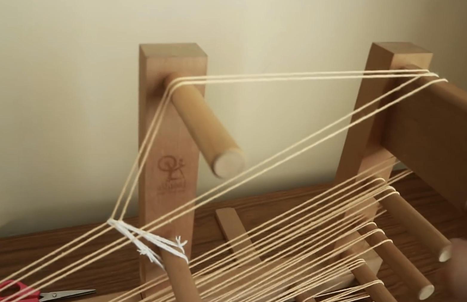
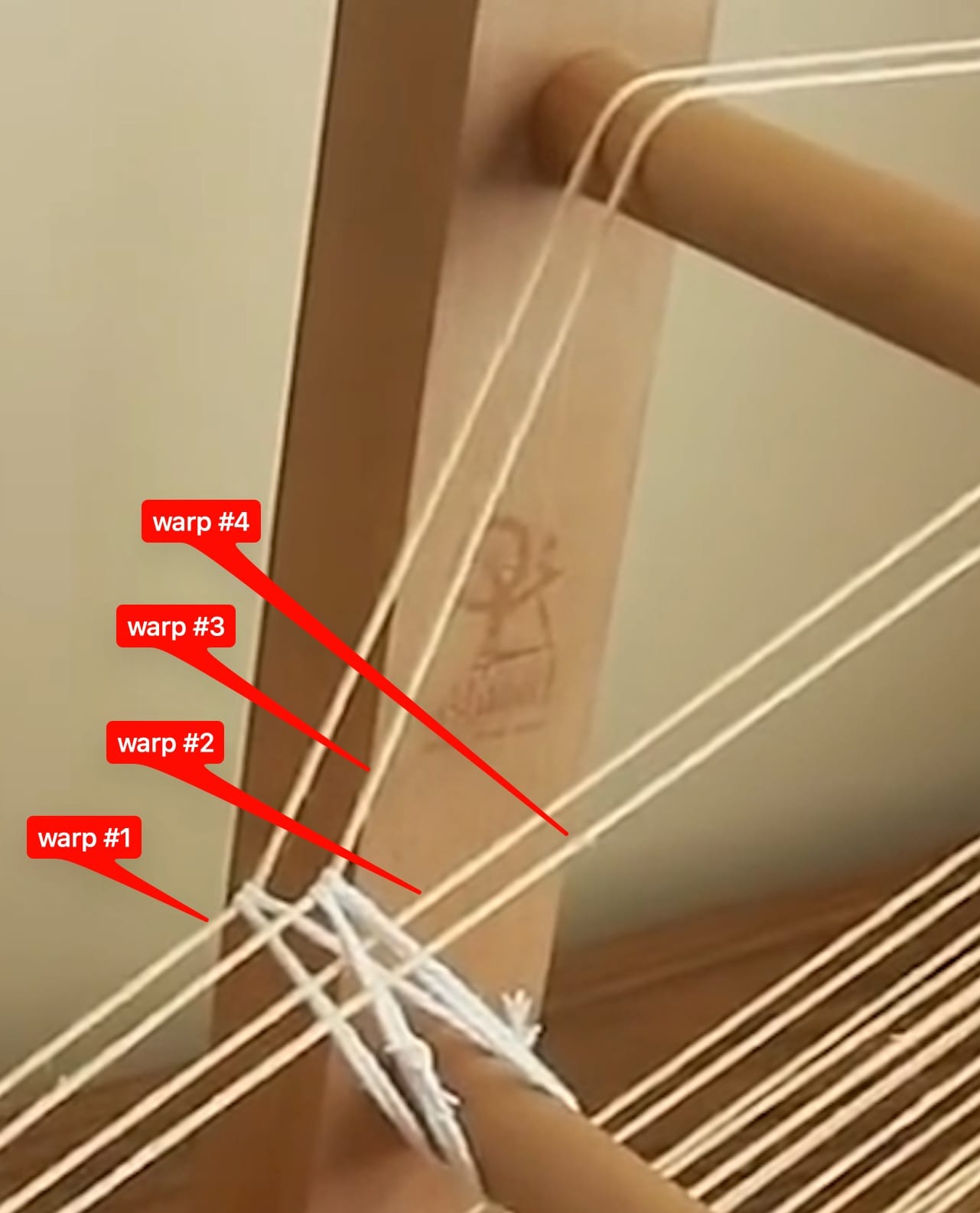
| Sizing a single heddle by tying a loop around top peg and heddle peg. | Extending the heddle from the heddle peg. | Wrapping heddle around wrap thread. | Securing heddle to heddle peg after wrapping. |
 |
 |
 |
 |
| With four warp threads in place. | Two are "heddle warp threads", two are "open warp threads." | |
 |
 |
 |
Sheds
|
|
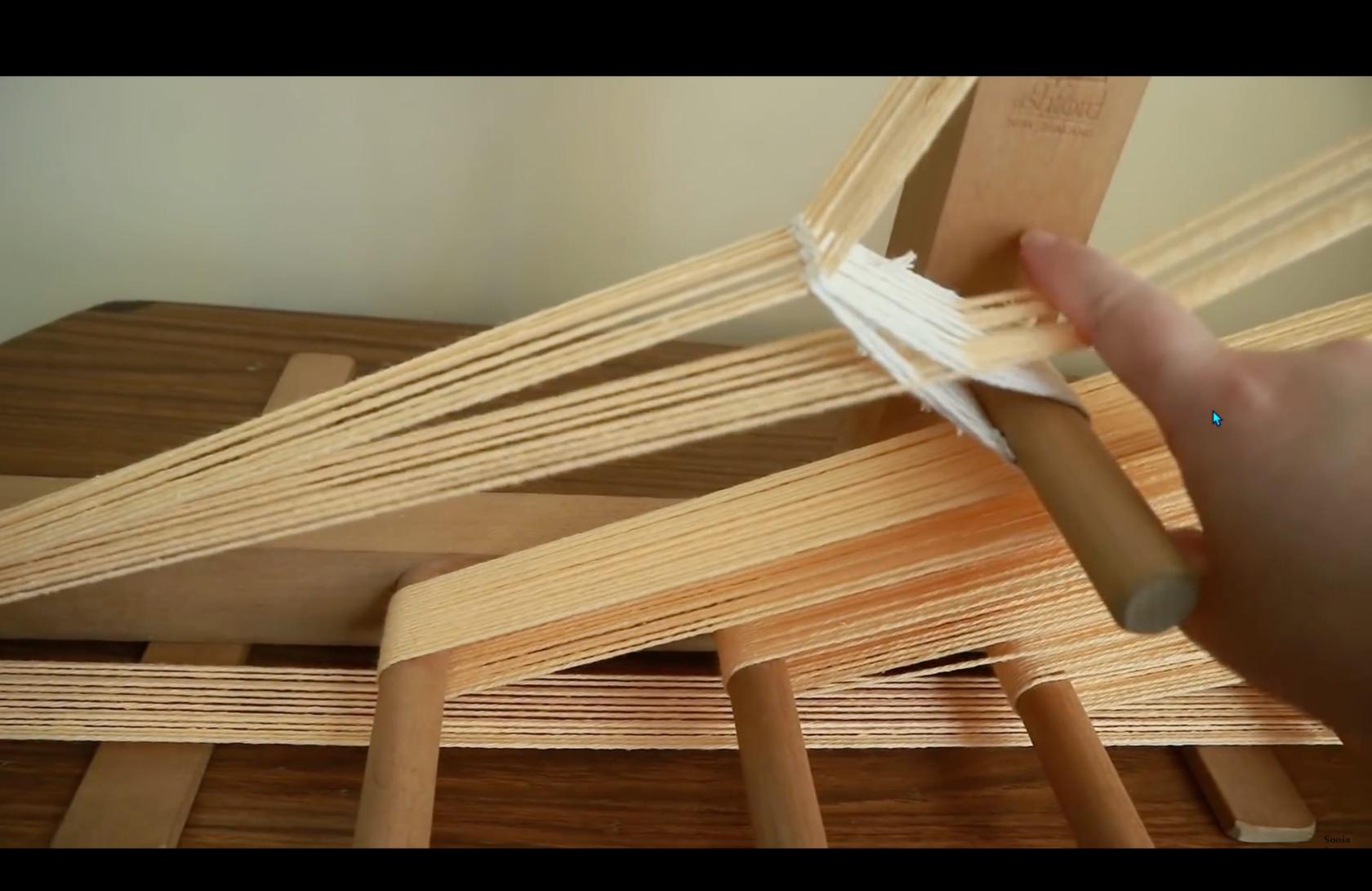
Shed below heddle warp threads. | |
|
|
 |
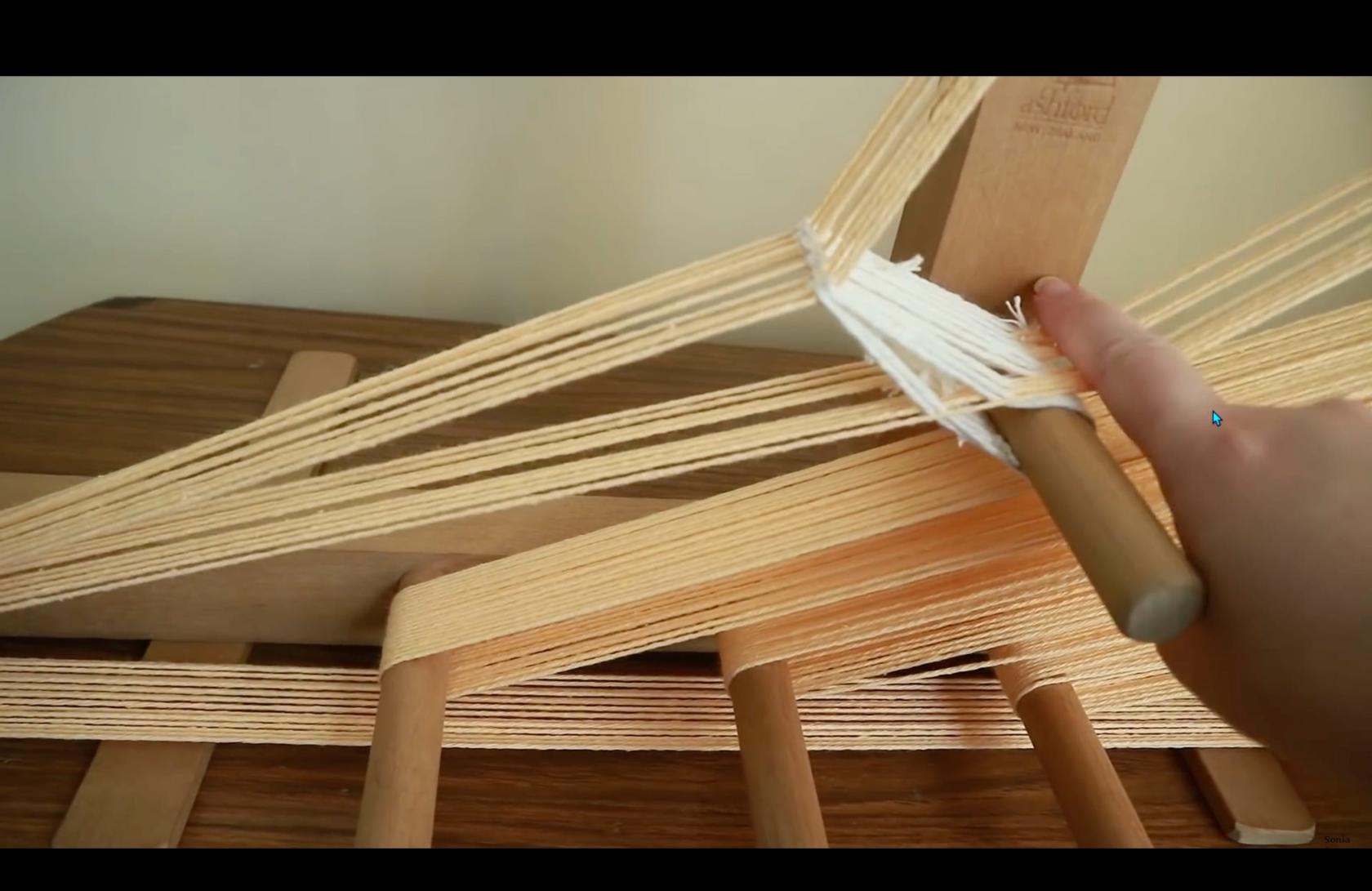 |
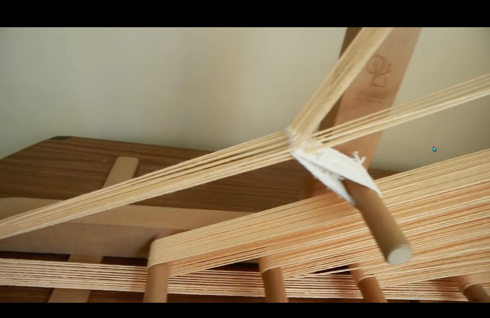
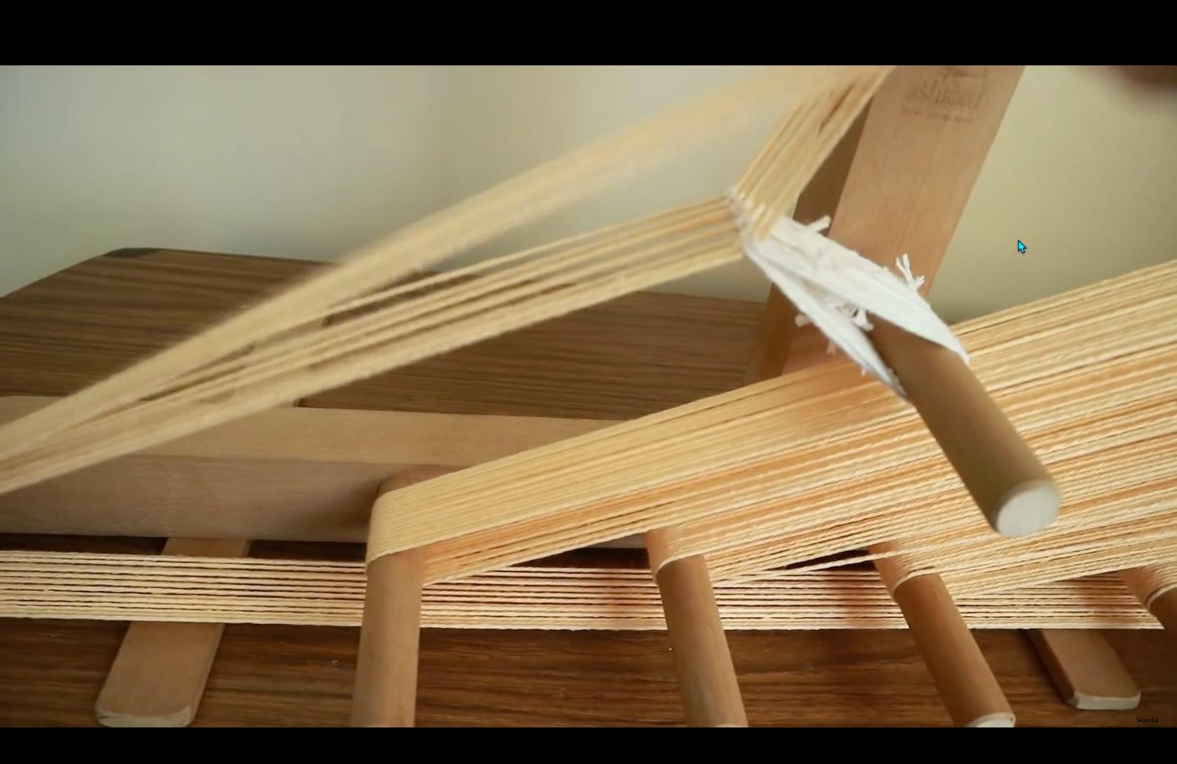
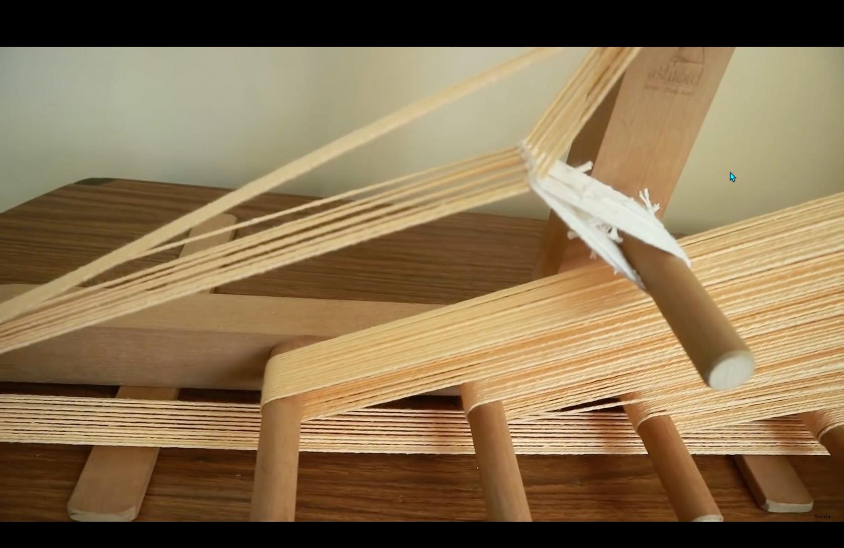
The heddle warp threads position are controlled by the heddle.
The open warp threads can be moved by hand, either below or above the heddle warp threads.
The space between the two sets of threads is called a "shed."
| Shed above heddle warp threads. | ||
 |
 |
 |
videos to review
https://www.youtube.com/watch?v=ZoOdTprcCVc
https://schachtspindle.com/products/inkle-loom
https://schachtspindle.com/collections/weaving-tools
https://www.youtube.com/watch?v=i2qNFV3YWJg
https://www.youtube.com/watch?v=2yy6saHjqC4
https://www.youtube.com/watch?v=zyLgy9VgRyY
https://www.youtube.com/watch?v=bMUxG4W4_tM
https://www.youtube.com/watch?v=OPpiyB0tDTg
https://threadcollective.com.au/blogs/weaving-looms/inkle-loom-weaving
https://littlelooms.com/inkle-on-the-fly-tips-for-easy-inkle-weaving/
https://www.instructables.com/Discover-and-Build-an-Inkle-Loom/
https://www.youtube.com/watch?v=PhzBMYzPVW0
https://www.youtube.com/watch?v=8nYpfku1Yjw
https://www.thecreativefolk.com/types-of-weaving-looms/